Today, Gain Machinery would like to share some inspection ways for precision machining metal part. Hopefully they are useful for you.
- Dimensional Inspection
- Calipers: Vernier calipers and digital calipers are widely used. They can measure the outer diameter, inner diameter, and length of the metal parts with an accuracy of up to 0.01mm – 0.02mm. For example, when machining a cylindrical metal shaft, calipers can be used to measure its diameter to ensure it meets the design requirements.
- Micrometers: They provide more accurate measurements than calipers. There are different types such as outside micrometers, inside micrometers, and depth micrometers. The accuracy of a high – quality micrometer can reach 0.001mm. When machining precision engine components, micrometers are often used to measure the critical dimensions like the thickness of piston rings.
- Coordinate Measuring Machines (CMMs): CMMs use a probe to measure points on the surface of a part in a three – dimensional space. They can measure complex geometries with high accuracy. The measured data is usually processed by software to generate detailed reports about the part’s dimensions. For example, in the aerospace industry, CMMs are used to inspect the precise dimensions of turbine blades.
- Surface Roughness Inspection
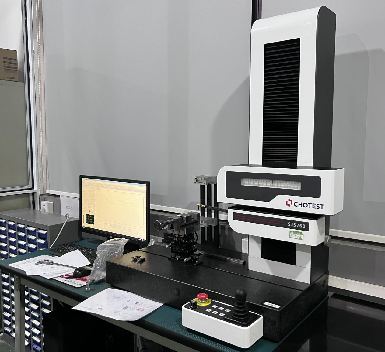
- Surface Roughness Tester: This instrument measures the roughness of the part’s surface by tracing a stylus over the surface. The roughness parameters such as Ra (arithmetical mean deviation of the profile) and Rz (maximum height of the profile) can be obtained. For precision – machined metal parts that require a smooth surface finish, like the surfaces of high – precision molds, surface roughness testers are essential to ensure the quality of the finish.
- Optical Microscopy: It can also be used to observe the surface texture and estimate the roughness. By magnifying the surface of the part, scratches, pits, and other surface irregularities can be detected. This method is useful for quickly assessing the overall quality of the surface finish before more precise measurements are made.
- Geometric Tolerance Inspection
- Dial Indicators: They are used to measure geometric tolerances such as run – out, concentricity, and flatness. For example, when machining a rotating part like a crankshaft, a dial indicator can be used to measure the run – out of the shaft to ensure it rotates smoothly within the specified tolerance range.
- Optical Comparators: These devices project an enlarged image of the part onto a screen, allowing inspectors to compare the part’s shape with a standard template. They are very useful for checking the profile and geometric features of complex – shaped parts. For example, in the production of gears, optical comparators can be used to check the tooth profile for accuracy.
- Material and Micro – structure Inspection
- Spectroscopy: It can be used to analyze the chemical composition of the metal part. For example, X – ray fluorescence spectroscopy (XRF) can quickly identify the elements present in the part and their proportions. This is important to ensure that the material used meets the design specifications.
- Metallography: Metallographic examination involves preparing a sample of the metal part, polishing it, and then observing its microstructure under a microscope. This can reveal information about the grain structure, presence of inclusions, and phase transformations. It helps to assess the quality of the material and the effect of the machining process on the material’s microstructure.

